Sunday, 30 December 2018

Eagle Surface Grinder MK3 Rebuild - Progress

This will be the last post for 2018. It has been an exciting year with life happening.

I finally managed to get some time to start the reassembling the Eagle Surface Grinder. All the surfaces have now been precision ground. All that is left to do is machine the oil grooves, match the dovetail surfaces, scrape the oil pockets, add the news spindle and ball screws, write some macros for the grbl g-code controller to behave like a surface grinder and the machine is ready for action.

Spindle and Drive Motor
After ordering and installing the new balls as described in a previous post, I am not satisfied with the resulting stiffness and pre-load design of the original spindle. The thinking now is to use a self contained spindle and machine an adapter sleeve. The new spindle axis diameter is 20mm compared to 25mm and the bearings considerably smaller, but for my needs this will be more accurate, even if I can only run 7" wheels. The motor in the base will drive a flat belt transmitting power to a love-joy style coupling in the "head stock" similar to old lathes with addition of the coupling if that makes any sense. Initially I wanted to go with poly V-Belts, but when I saw the very modern Schaublin 102 N-VM-CF still uses crown pulleys and flat belts. I started investigating the advantages of flat belts. The main advantages I could find was, better efficiency, less vibration, and higher speeds. not sure if any of this holds true, but worth a try. Here I will need to design the housing at the back of the spindle housing, which will hold the crown pulley and shaft coupling, for driving the spindle. A direct drive would be more efficient, economical with less vibration, but that would have the motor extend  at the back of the spindle housing, similar to the later eagle model shown below, in a small shop not an option.


Knee Oil groves

On the MK3 model the only the table sports oil groove. As discussed in a previous post, I have decided to go with the zig-zag oil grove pattern, it is more time consuming to machine, but should give better results. Below some images on the layout and machining process. The fixed dovetail had a ridge, where it meets the flat surface on the knee, this had me confused for some time as to why I do not get full bearing on the entire flat surface. a few head-scratches later I used a carbide ball nose end mill to machine some clearance in the corner, all this with a portable hand drill. The only straight edge I could find to fit the angled recess was a carpenters knife blade, this worked great!

Ball Screws /Servo/Stepper Motor
The ACME lead screw needs to be replaced, it has a lead of 10 TPI. I do not feel like cranking the hand wheel so installing a feed motor is a given. Sourcing an ACME 1-1/4" x 10TPI  or similar in my part of the world is not feasible. So I opted to go full CNC and use 5mm pitch ball screws.  After doing some calculations on THK ball screw specifications with a combined load of 100kg., a 20mm diameter screw will work within load ratings, if a maximum sliding speed of 38mm/s is not exceeded. For a 5mm pitch screw this will give maximum motor speed of 456 rpm. And 8NM motor would be required for https://www.nidec.com/en-EU/technology/calc/torque/ballscrew/ to drive this load.

Sunday, 1 July 2018

Deckel FP2 restoration Year 1966, Serial # 5151

Almost two years since I got the machine, and many hours later, the restore is complete. Thanks to www.metalworker.eu, Bruce and some other helpful fellows at https://www.practicalmachinist.com/vb/deckel-maho-aciera-abene-mills/deckel-fp2-1966-restoration-321812/

The machine runs incredibly quiet and is an absolute pleasure to use!


Saturday, 30 June 2018

Surface Speeds - for the Deckel FP2


No more fiddling with a calculator


RPM settings and corresponding surface speeds

Ranges are for HSS tools, extracted from the SO single lip cutter grinder manual. For me, this this is a good starting point for simple cutters. Modern geometries are specified by the manufacturer.

More reading
http://www.stahl-online.de/wp-content/uploads/2013/10/MB137_Zerspanen_von_Stahl.pdf

Sunday, 3 June 2018

Lathe V Ways Calculation for fitting Tailstock and Carriage _/\_

While rebuilding the Chipmaster, the problem of aligning the carriage bed ways ( bottom slide ) and top slide arise, from what information I can find these have to be at right angles. The bottom slide is worn bananas, so a simple spotting technique, on the bed might cause a lot of headache later to align the cross slide. So I decided to align the tail stock base first, and then use it on the lathe to check which original sufaces on the crosslide are closest to allignment, to be used on the mill setup.  I will then cleanup the V groves at the bottom, and do the final spot checking on the lathe beds. So the approach requires three steps.
1) Align the tail-stock on the mill, and touch-up the V slot, and flat surface. Machine one outside surface parallel to the V-Groves. Final fit on the lathe with transfer spotting.

2) Find the best reference surface on the carriage with the fitted tail-stock base as guide. Or bolt an adjustable bar to the back, where the taper attachment usually attaches.

3) Machine the cross-slide base V and flat ways, aligned to identified surface. Fit with transfer bluing.

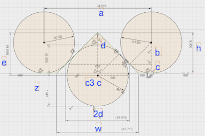
The calculation for the depth of the V slots require similar math to that used for dovetail calculations. I used two 14 mm end mills as gauge pins, the bottom circle is used for measuring the depth, when the base is upside down on the mill, since I want to do the machining in one setup.

Height with14mm gauge pin in V slot, should be z higher than flat surface          
              
On the drawing, the top two 14mm gauge pins are used to  measure the_ /\_ ways, the
bottom gauge pin is used to measure height over the flat surface, for a level tail stock base.          
              
map the flat surface to find low points, add z, mill out v until this height is reached          
mill down flat surface         


                 measured    38,515    across pins
c1,c2,c3    r    7   
                 a    24,515    measured-2r
                 b    4,949747468   
                 c    2,050252532    r-b
                2d    14,61550506   
                d    7,307752532   
                h    9,358005063    c+d
               w    18,71601013    2*height
               e    9,899494937   
              c3    center    0,541489873    e-h
              z    7,541489873    r+c3 center

Sunday, 20 May 2018

Quadrature decoder ideas for glass scales and rotary encoders on Arduino and AVR

Ever wonder how the Heidenhain glass scales, can measure at increments of 0,5 µm? if the graduation on the scale is only 20um? If you come from the digital world, there are four transitions so the minimum should be 4um.
This mystery made me read up on the Heidenhain signals 1VPP or 11 µAPP ( 1VSS, 11 µASS ) These are analog signals, if you read the older literature it becomes clear that photo sensitive devices are used to generate the current, the 1Vpp signals are probably pre-loaded with a 90ohm resistor. 
Vernier scales are similar, so are modulation techniques like QAM, QPSK. With glass scales there is no amplitude or phase modulation on top of the carrier, only two orthogonal signals, the rotational relationship between the two base-band signals (I/Q) translates to position, speed and velocity. 
So what advantages do analog signals have over digital? The states are infinite, limited only by noise. But how to extract infinite states from two orthogonal signals? Run them through an AD converter and calculate the angle., this will work but the system response is limited by conversion rate and calculation performance.

Investigating further I stumbled on CORDIC https://en.wikipedia.org/wiki/CORDIC

With a search for CORDIC Quardrature decoder, I found various other methods of Sine/Cosine to Digital Conversion
http://www.ichaus.de/upload/pdf/WP7en_High-Precision_Interpolation_140124.pdf

  Flash Conversion

 Vector -Tracking Conversion

 SAR Conversion with Sample-and- Hold Stage

 Continuous -Sampling A/D Conversion
Out of pure curiosity, I will implement the continuous sampling conversion with CORDIS lookup on the Arduino, and perhaps try the vector tracking conversion on the Attiny2313
Should this work, I will try to convert my Sino Digital scales to analog and see what accuracy I can achieve. Perhaps even build a Heidenhain scale interface for the Touch DRO Project.

Resources 

CORDIC


https://eprints.soton.ac.uk/267873/1/tcas1_cordic_review.pdf

https://www.mikrocontroller.net/articles/AVR-CORDIC

Linear interpolation

https://www.mikrocontroller.net/articles/AVR_Arithmetik/Sinus_und_Cosinus_(Lineare_Interpolation) 

Fast Sampling on AVR
http://yaab-arduino.blogspot.com/2015/02/fast-sampling-from-analog-input.html


http://wiki.linuxcnc.org/cgi-bin/wiki.pl?ResolverToQuadratureConverter


Tuesday, 15 May 2018

Useful code snips for working with XML, CSV, and other flat file formats in perl, groovy, python, java, c, c++

Lock files in Windows batch scripts, avoid more than one instance running

REM Check if another instance is running, and exit if true
IF EXIST ".lock" exit 0

echo Batch file start at %time% %date% by %username%.> .lock

REM Script processing starts here

REM Script processing ends here
del .lock


Replace XML tag data with Perl

use strict;
use warnings;
use XML::Twig;

for ( glob "*.xml" ) {
        print "process file $_\n";

XML::Twig->new(
    pretty_print  => 'indented',
    twig_handlers => {
         PaymentAmount => sub {
            $_->set_text( '0' )->flush
        },
    },
)->parsefile_inplace( $_, 'orig_*' );

Groovy and Tokenize or Split

While using tokenize() if you want to discard fields or lines with no data might work as such,

List myList =  inputStream.getText().tokenize("\n\r")

it can not be used if you want to retain the offset format of CSV or pipe delimited fields, since it will not yield the entries with no data.

As example the second field will be discarded. "Line1"|"""|"Name"

Here we will need to use split

List lHeader = sHeader.split("\\|")

Another odd behavior is if you split with a pipe without escapes, "|", split returns an array of characters. This is probably documented, but I did not have the time yet to read all the documentation and can not find any reference to this behavior.

Sunday, 15 April 2018

Howto on the Horizontal Milling Machine - My notes

Comparing a Deckel FP2 to metal shapers, makes me think they are related, part of the evolution of machine tools. Still want to build the clapper box to fit the deckel...

The problem with the quagga or dodo is they have been extinct for a long time, how they once lived and roamed, we know from information passed down by generations. Very similar to me is the concept of the vertical milling machine, almost extinct; and not a lot of information around on how to use it!?

With the old fossil standing in front of you, and me time traveling with my leather apron, old classics humming on the valve amplifier, I force myself to only use the vertical head, and start thinking how to cut angles as example, it becomes clear; a simple but very useful geometry.

Since very little information is available online, I hope to collect a useful how to guide for starters, and perhaps also gather some expert advice in the field.

In a previous post I presented my idea to cut oil groves with a cutting jig, the jig has to have three sides with angles. How to do this with the vertical head, without sine bar? It would be possible with a swivel base vice if the cutter was very slim and long, not ideal or even possible, sequence of operation becomes important. But on a horizontal setup this becomes easy. Set the angle on the base, flip the part upright, cut the first angle, lay it flat for cut two, flip it over and cut third side. Or reverse the order no problem. Only have a short stubby cutter? also no problem.


Saturday, 14 April 2018

Simple Arduino based DRO design ideas

My thinking is to create modular units, a display controller with 4 inputs to display the three axis and RPM. It should be small and later connect to Linux CNC

Displays

Pollin WDC2704
Pollin Hyundai HP12542R-DYO

TM1638

https://github.com/rjbatista/tm1638-library

Quadrature encoder
HCTL2000
Attiny2313
https://github.com/usedbytes/i2c_encoder


VFD Contol
https://wapl.es/cnc/2015/12/04/huanyang-linuxcnc-2.7-speed-control.html


The Arduino nano does not have enough pins to address 4 Quadrature counter IC's, IO expander Atmega32 or 8255?

http://www.torretje.nl/files/p8255optim.ino

Decide on a bus RS232? I2C?

Sunday, 8 April 2018

Oil grooves for sliding surfaces on Machine Tools / Ölschmiernuten für Gleitführungen an Werkzeugmaschienen

My ongoing quest to restore the Deckel FP2, Chipmaster and Eagle surface grinder, makes you deep dive into Machine tool design frequently.

Once the castings where back with shiny new precision ground sliding ways, the question comes do I improve on some of the shortcomings, like no oil grooves? Or leave it factory standard? Well this is probably one of the main reasons why I decided invested in old machine tools, the new machines from china also require a fair amount of work to perform consistently and last for some time.... Might as well spend the time on an old machine tool and in the process learn the trade.

Well back  to the topic at hand, how to cut the oil grooves inside dovetails? There are various tidbits on the web giving advice, but nothing seemed elegant and time efficient. As example one could spend a lot of time with a precision setup on the manual milling machine to engrave oil grooves. Or a setup on a CNC. Or use a hand held dremel like tool, or use a custom ground scraping tool.


When you consider the options, it becomes apparent why a lot of old machines, have very simple oil grooves like elongated Z's,  straight connected 0's, long straight slots with perpendicular grooves similar to I. A few examples shown below.


Image result for oil grove machine tool

Image result for oil grove machine tool

But we know better, there is a great book by M Weck ( Werkzeugmaschinen 2 - Konstruktion und Berechnung ) Pg 245 it shows some examples and the form which shows best performance, a trapezoidal zig zag form (figure 1 below) When you think about what happens to the viscus fluid while the slides are sliding across one another back and forth, this almost acts as a staged pump.  The pumping action helping the spread of oil, since it can not run back along the inclined grooves. The one thing my research did not find is the best angle for the inclined grooves. The angle needs to satisfy two opposing requirements, retain as much oil to evenly spread on the opposing slide, 2. feed oil to the next stage. My starting point is 25͒͒͒͒͒͒°, lets see how this goes.


Image result for oil grove machine tool


Now once the form is selected, the down side is this form probably is the most complex to produce. This made me go in search of methods we used before machine tools, and the result is a simple tongue and grove planer with a special ground tip.  Below take one on such a tool, for 60° dovetails. The angle might vary on your specific requirement, but I can see a use in inverted V slides used on the lathe and in square columns used in the Deckel.


Sunday, 11 March 2018

Engraving a cylinder with graduations to be used as machine tool / lathe dial.


Using gcmc to generate the gcode, this becomes a trivial exercise in more modern programming techniques.

feedrate(400.0mm);

sf = 10.0mm;    /* Scaling factor */
diameter = 80.0mm;      /* Scaling factor */

n = 0;

for (c=0deg; c<360deg ; c=c+3.6deg ) {
// message(">>>> ", c, " ",c%36);

 if ( ( c % 36 ) == 0deg || ( c % 36 ) == 36deg) {
 message("--- ", n);
 vl  = typeset(to_string(n), FONT_HSANS_1);
 vl = scale(vl, [sf / (2.0*pi()), sf]);
 n = n + 10;
 goto([diameter/2,-,0.0mm,-,-,c]);
 move([-,-,14.0mm,-,-,-]);

 }
 elif ( ( c % 36 ) == 18deg ) {
 message("--  ", c);
 goto([diameter/2,-,0.0mm,-,-,c]);
 move([-,-,10.0mm,-,-,-]);
 }
 elif ( ( c % 36 ) != 0deg || ( c % 36 ) != 18deg  ) {
 message("-   ", c);
 goto([diameter/2,-,0.0mm,-,-,c]);
 move([-,-,7.0mm,-,-,-]);
 }
}

Interesting site with lathe dial reductions to suit different lead screws.
http://www.modelengineeringwebsite.com/Mini_handwheel_1.html

Typical operations implemented for the mini CNC Lathe


Linux CNC forum resource with  handy macros
https://forum.linuxcnc.org/41-guis/26550-lathe-macros

Threading
http://wiki.linuxcnc.org/cgi-bin/wiki.pl?Lathe_Code

 
Engraving numbers on cylinders
https://forum.linuxcnc.org/20-g-code/27169-g-code-to-engrave-numbers-on-cylinders?limitstart=0


Mini Lathe CNC Conversion

The requirements is simple, for my Deckel and Eagle restore I need to make new dials and dial fasteners. The dial fasteners are simple and a knurled part will probably do, but I want it to look as original as possible. These are plastic rings about 80mm diameter with formed surface resembling a toothed drive belt pulley. I need to make four of these, setup in the dividing head and mill all of them at once, then slice them up and cut the internal thread, was my initial thinking. 

But wait I have a ball screw, steppers and a  mini lathe, a small 7 x10 branded  Rotwerk.

This seemed like the ideal opportunity to finally convert the little lathe to CNC.

I need a fourth axis. So the spindle has to double as A Axis. This was done with big 120tooth HTD 3M pulley which is attached directly on the spindle.

Converting the Z axis or bed slide was simple, just replace the lead screw with the ball screw and stepper mount.

The A Axis is a bit more challenging, but also a fairly quick job.

Next configuring Linux CNC, wiring the parallel port and stepper drivers. all this was accomplished in less than two hours.

I will post some pictures shortly.

G-code for engraving 0 to 360 degrees on a cylinder


; Main routine for engraving 0 to 360 degrees on a cylinder
; Based on work done by Andy Pough, transposed to C and Z axis for my mini lathe conversion
; Subroutines not included as they are the same as in my previous post

 O100 while [#3 LT 360]
 #4 = [#3 * #<_scale>]
(DEBUG, #4)
 O101 if [#4 LT 10]
        G0 C#3 Z0 X[#<_dia> / 2 + 1]
        O[FIX[#4]] call
 O101 else if [#4 LT 100]
        G0 C[#3 - #42 * 0.5] Z0 X[#<_dia> / 2 + 1]
        O[FIX[#4 / 10]] call
        G0 C[#3 + #42 * 0.5] Z0
        O[FIX[#4 mod 10]] call
 O101 else if [#4 LT 1000]
        G0 C[#3 - #42 ] Z0 X[#<_dia> / 2 + 1]
        O[FIX[#4 / 100]] call
        G0 C#3 Z0
        O[FIX[[#4/10] mod 10]] call
        G0 C[#3 + #42 ] Z0
        O[FIX[#4 mod 10]] call
 O101 endif

 #3 = [#3 + #<_inc>]
 O100 endwhile

G-Code for Lathe Dial Rings 100 Increments

;Attempt to engrave scale rings based on the work done by Andy Pugh at https://forum.linuxcnc.org/20-g-code/27169-g-code-to-engrave-numbers-on-cylinders?limitstart=0

;Engraving is done in the ZC plane
;Warning, this is work in progress

#<_dia> = 50 ; scale diamter
#<_depth> = 0.2 ; engraving depth
#<_height> = 2 ; character height
#<_scale> = 1 ; unit conversion
#<_inc> = 3.6 ; angle between marks
#<_feed_soll_wert> = 20 ;

G21

F #<_feed_soll_wert>

#41 = [180 / [#<_dia> * 3.14159] * #<_height>]
#42 = #<_height>
(debug, #41 #42)

;Subroutine for engraving # 0
O0 sub
 G92 C0 Z0
 G0 C0 Z0 X[#<_dia> / 2 + 1]
 G1 X[#<_dia> / 2 - #<_depth>]
 C[0.2357 * #41] Z[0.0976 * #42]
 C[0.3333 * #41] Z[0.3333 * #42]
 C[0.3333 * #41] Z[0.6667 * #42]
 C[0.2357 * #41] Z[0.9024 * #42]
 C[0.0000 * #41] Z[1.0000 * #42]
 C[-0.2357 * #41] Z[0.9024 * #42]
 C[-0.3333 * #41] Z[0.6667 * #42]
 C[-0.3333 * #41] Z[0.3333 * #42]
 C[0.0000* #41] Z[0.0000 * #42]
 G0 X[#<_dia> / 2 + 1]
 G92.1
O0 endsub


;Subroutine for engraving # 1
O1 sub
 G92 C0 Z0
 G1 X[#<_dia> / 2 - #<_depth>]
 C[0.0000 * #41] Z[1.0000 * #42]
 G0 X[#<_dia> / 2 + 1]
 G92.1
O1 endsub

;Subroutine for engraving  storke
; Oline [length]
O100 sub
 G92 C0 Z0
 G1 X[#<_dia> / 2 - #<_depth>]
 C[0.0000 * #41] Z[1.0000 * #1]
 G0 X[#<_dia> / 2 + 1]
 G92.1
O100 endsub

;Subroutine for engraving # 2
O2 sub
 G92 C0 Z0
 G0 C[0.3333 * #41] Z[0.000 * #42] X[#<_dia> / 2 + 1]
 G1 X[#<_dia>/2 - #<_depth>]
 C[-.3333 * #41] Z[0.0000 * #42]
 C[0.0000 * #41] Z[0.3333 * #42]
 C[0.2357 * #41] Z[0.4310 * #42]
 C[0.3333 * #41] Z[0.6666 * #42]
 C[0.2357 * #41] Z[0.9024 * #42]
 C[0.0000 * #41] Z[1.0000 * #42]
 C[-.2357 * #41] Z[0.9024 * #42]
 C[-.3333 * #41] Z[0.6667 * #42]
 G0 X[#<_dia> / 2 + 1]
 G92.1
 O2 endsub

;Subroutine for engraving # 3
O3 sub
 G92 C0 Z0
 G0 C[-.3333 * #41] Z[0.3333 * #42] X[#<_dia> / 2 + 1]
 G1 X[#<_dia>/2 - #<_depth>]
 C[-.2357 * #41] Z[0.0976 * #42]
 C[0.0000 * #41] Z[0.0000 * #42]
 C[0.2357 * #41] Z[0.0976 * #42]
 C[0.3333 * #41] Z[0.3333 * #42]
 C[0.2357 * #41] Z[0.5690 * #42]
 C[0.0000 * #41] Z[0.6667 * #42]
 C[0.3333 * #41] Z[1.0000 * #42]
 C[-.3333 * #41] Z[1.0000 * #42]
 G0 X[#<_dia> / 2 + 1]
 G92.1
O3 endsub

;Subroutine for engraving # 4
O4 sub
 G92 C0 Z0
 G0 C[0.2357 * #41] Z[0.000 * #42] X[#<_dia> / 2 + 1]
 G1 X[#<_dia>/2 - #<_depth>]
 C[0.2357 * #41] Z[1.0000 * #42]
 C[-.3333 * #41] Z[0.3333 * #42]
 C[0.3333 * #41] Z[0.3333 * #42]
 G0 X[#<_dia> / 2 + 1]
 G92.1
 O4 endsub

;Subroutine for engraving # 5
O5 sub
 G92 C0 Z0
 G0 C[-.3333 * #41] Z[0.3333 * #42] X[#<_dia> / 2 + 1]
 G1 X[#<_dia>/2 - #<_depth>]
 C[-.2357 * #41] Z[0.0976 * #42]
 C[0.0000 * #41] Z[0.0000 * #42]
 C[0.2357 * #41] Z[0.0976 * #42]
 C[0.3333 * #41] Z[0.3333 * #42]
 C[0.2357 * #41] Z[0.5690 * #42]
 C[0.0000 * #41] Z[0.6667 * #42]
 C[-.3333 * #41] Z[0.6667 * #42]
 C[-.3333 * #41] Z[1.0000 * #42]
 C[0.3333 * #41] Z[1.0000 * #42]
 G0 X[#<_dia> / 2 + 1]
 G92.1
O5 endsub

;Subroutine for engraving # 6
O6 sub
 G92 C0 Z0
 G0 C[-.3333 * #41] Z[0.0333 * #42] X[#<_dia> / 2 + 1]
 G1 X[#<_dia> / 2 - #<_depth>]
 C[-.2357 * #41] Z[0.5690 * #42]
 C[0.0000 * #41] Z[0.6667 * #42]
 C[0.2357 * #41] Z[0.5690 * #42]
 C[0.3333 * #41] Z[0.3333 * #42]
 C[0.2357 * #41] Z[0.0976 * #42]
 C[0.0000 * #41] Z[0.0000 * #42]
 C[-.2357 * #41] Z[0.0967 * #42]
 C[-.3333 * #41] Z[0.3333 * #42]
 C[-.2357 * #41] Z[0.9024 * #42]
 C[0.0000 * #41] Z[1.0000 * #42]
 C[0.2357 * #41] Z[0.9024 * #42]
 G0Z [#<_dia> / 2 + 1]
 G92.1
 O6 endsub

;Subroutine for engraving # 7
O7 sub
 G92 C0 Z0
 G0 C[-.2357 * #41] Z[0.0000 * #42] X[#<_dia> / 2 + 1]
 G1 X[#<_dia>/2 - #<_depth>]
 C[0.3333 * #41] Z[1.0000 * #42]
 C[-.3333 * #41] Z[1.0000 * #42]
 G0 X[#<_dia> / 2 + 1]
 G92.1
O7 endsub

;Subroutine for engraving # 8
O8 sub
 G92 C0 Z0
 G0 C[0.2357 * #41] Z[0.5690 * #42] X[#<_dia> / 2 + 1]
 G1 X[#<_dia> / 2 - #<_depth>]
 C[-.2357 * #41] Z[0.5690 * #42]
 C[-.3333 * #41] Z[0.3333 * #42]
 C[-.2357 * #41] Z[0.0976 * #42]
 C[0.0000 * #41] Z[0.0000 * #42]
 C[0.2357 * #41] Z[0.0976 * #42]
 C[0.3333 * #41] Z[0.3333 * #42]
 C[0.2357 * #41] Z[0.5690 * #42]
 C[0.3333 * #41] Z[0.6667 * #42]
 C[0.2357 * #41] Z[0.9024 * #42]
 C[0.0000 * #41] Z[1.0000 * #42]
 C[-.2357 * #41] Z[0.9024 * #42]
 C[-.3333 * #41] Z[0.6667 * #42]
 C[-.2357 * #41] Z[0.5690 * #42]
 G0 X[#<_dia> / 2 + 1]
 G92.1
O8 endsub

;Subroutine for engraving # 9
O9 sub
 G92 C0 Z0
 G0 C[-.3333 * #41] Z[0.3333 * #42] X[#<_dia> / 2 + 1]
 G1 X[#<_dia>/2 - #<_depth>]
 C[-.2357 * #41] Z[0.0976 * #42]
 C[0.0000 * #41] Z[0.0000 * #42]
 C[0.2357 * #41] Z[0.0976 * #42]
 C[0.3333 * #41] Z[0.3333 * #42]
 C[0.3333 * #41] Z[0.6667 * #42]
 C[0.2367 * #41] Z[0.9024 * #42]
 C[0.0000 * #41] Z[1.0000 * #42]
 C[-.2357 * #41] Z[0.9024 * #42]
 C[-.3333 * #41] Z[0.6667 * #42]
 C[-.2357 * #41] Z[0.4310 * #42]
 C[0.0000 * #41] Z[0.3333 * #42]
 C[0.2357 * #41] Z[0.4310 * #42]
 C[0.3333 * #41] Z[0.6667 * #42]
 G0 X[#<_dia> / 2 + 1]
 G92.1
O9 endsub

; Start Engraving

G92.1
#3 = 0

O500 while [#3 LT 360] ; rotate through full 360 degrees

 #4 = [#3 * #<_scale>]

 (DEBUG, #4)
 #5 = [#3 MOD 36]

 O501 if [#5 EQ 0] ; marks at 10th increment
        G0 C#3 Z0 X[#<_dia> / 2 + #<_depth>]
        O100 call [8]                       ; engrave long line
;       O[FIX[#4]] call
        O0 call
;       G0 C#3 Z0

 O501 else if [#5 EQ 18] ; marks at 5th increment
;;      G0 C[#3 - #42 * 0.5] Z0 X[#<_dia> / 2 + 1]
        G0 C#3 Z0 X[#<_dia> / 2 + #<_depth>]
        O100 call [6]                       ; engrave medium line
        O5 call
;       O[FIX[#4 / 10]] call
;       G0 C[#3 + #42 * 0.5] Z0
;       O[FIX[#4 mod 10]] call

; O501 else if [[#5 MOD 1 ] GT 0 ] ; minor ticks

;       G0 C[#3 - #42 ] Z0 X[#<_dia> / 2 + 1]
        G0 C#3 Z0 X[#<_dia> / 2 + #<_depth>]
;        O100 call [4]                       ; engrave short line

;       O[FIX[#4 / 100]] call
;       G0 C#3 Z0
;       O[FIX[[#4/10] mod 10]] call
;       G0 C[#3 + #42 ] Z0
;       O[FIX[#4 mod 10]] call
 O501 endif

 #3 = [#3 + #<_inc>] ; increment loop counter

O500 endwhile

M2

Sunday, 25 February 2018

Measurement techniques for precision bearing balls

While rebuilding the Eagle surface grinder, I have to refurbish the spindle bearings. One of the challenges is to select matching bearing balls as accurately as possible.

Googling around, I could not find any information on how to do this with simple tools in the home shop. Some commercial methods which come to mind are using an optical comparator or 3d laser scanner. While taking myself and the dogs for a walk this morning at 5:30, I realised, like many times before; the old school machinists did not have all the fancy measuring equipment we have noways, yet managed to build very accurate and precise machines.  The idea of tolerance measurement similar to how snap gauges work came to mind.

To do this one has to measure the ball diameter. There are a few methods I can come up with to do
this. The intention is to measure diameter as accurately as possible, not just variations in the Lot or precision.


Tool Method Accuracy Repetability Issues
Micrometer place the ball between the anvil and measure Good Fair Measuring Force
Dial indicator Capture ball on stand, compare height of balls. Relative Good Allignment
Slip Gauge Build gate on surface plate with high and then low tolerance,
roll balls through the gate
Best Best Cleanliness


In a previous post I have described the calculations and selection of ball diameter. For reference, I am working with Grade 10 Balls, 13/32" or 10.31875mm


Grade Sphericity [mm] Lot diameter variation [mm] Nominal ball diameter tolerance [mm] +/- Maximum surface roughness (Ra) [µm]
10 0.00025 0.00025 0.0013   0.025

My method will firstly select balls which roll under the gauge block stack bridge setup for the high tolerance level of 10.32005mm, and then from this selection set, select the balls which do not pass under the low tolerance stack of 10.31745 mm. This is the simplest, and most accurate and precise method I could think of  for the home shop machinist.

Great resource with lots of useful information:
http://www.precisionballs.com/Ball_diameter_Calibration.php
http://www.precisionballs.com/Ball_Diameter_Errors.php

Sunday, 28 January 2018

Eagle Surface Grinder Model 3 Rebuild - Spindle Refurbish

My MK3 is almost as described by Tony on lathes.co.uk/eagle
with one difference, at the back there are two deep grove ball bearings.


He writes:
Sized imperially, the ball races consisted of two opposed angular contact ball bearings behind the wheel with a single deep groove ball bearing at the drive pulley (rear) end. Interestingly, if the angular contact bearings are dismantled (they push apart) an owner reports that they can be revived by polishing the races lightly with diamond paste, fitting new balls and lubricating with ordinary lithium grease.

The spindle of my variant runs in two angular contact bearings, each pair in back to back (DB) arrangement. The preload adjustment is not clear, need to do more research here. The bearings are of imperial dimensions ID 25.4 OD 63.5 ( 1" x 2.5" ). 
The spindle assembly is pulled out to the front, there is a hole in the middle to restrain the shaft from rotating.
Once out, the bearings pull apart and the balls measure in at 10.30 mm since this is an imperial sized bearing my thinking is this was probably a 13/32" ball. (10,31875mm ). Initial measurements of the races ID and OD confirm this.

I could not find a suitable new replacement for the Bearings.
The replacement is still manufactured under the following names from R&M, SKF and some other brands.

RMS8    MJ1 - Deep Grove
AMS8    MJT1 - Angular Contact


Since the bearings show significant wear, there are two options under consideration.

1) Use 7006 bearings 30x55mm and machine new sleeves to fit the 1" shaft and 2.5" outer seat.

2) Do what  Tony describes. Order new balls, polish the races and see what I get.

Sunday, 14 January 2018

Eagle Surface Grinder Model 3 Rebuild - Planning

The surface grinder is made up of the following precision guided parts, a vertical column, a knee, a cross slide saddle, and a horizontal table.

The machine is build in a typical column knee setup as seen in horizontal milling machines.
The column has two parallel and one perpendicular planes.
The knee has two perpendicular planes.
The cross slide has two perpendicular and two parallel planes
The horizontal table has on plane

Starting at the biggest surface first and then working my way back seems to make the most sense. This includes all surfaces on a specific component. ordering the components by guide ways surface area yields this sequence.
  • Vertical Column 2 x 800x50mm flat+ 2 x 800x30mm Dovetails
  • Knee  2x300x50mm flat + 2x300x50 dovetail + 2x400x50 flat + 1x400x50 dovetail
  • Table 2x 800x50mm flat + 2x 800x50mm dovetail
  • Cross slide 2x 200x30 flat + 1x200x30mm dovetail + 2x400x30mm flat + 1x400x30mm dovetail
  • Gib's with two surfaces 60Deg, 3 x

Planned steps and sequence:
  • The table was surface ground to be used as a template.
  • Build a holder for all three angular flat gib's 
  • Scrape in all flat and angled surfaces of the gib's so they can be used for templates later.
  • Build indicator jig for measurement, geometry and dimensions to provide 3 point contact to measure all surfaces in need of scraping
  • Scrape Column front side flat, using the feed table, this will preserve the original machined surface on the center of the column. indicator jig should provide 3 points of contact on the original machined surface and two on the dovetail surface, to measure dovetails.
  • pre scrape knee vertical slides with straight edge or gib as template.
  • align vertical and scrape horizontal slides of knee on surface plate
  • pre scrape knee right side dovetail using the knee's gib as template.
  • Fit knee on column and scrape column dovetails to match,
  • finish scrape knee vertical slides.
  • pre scrape cross slide flat ways and align on surface plate
  • pre scrape dovetail ways using the gib's as templates
  • scrape knee side on cross slide using the knee as template, align to column.
  • scrape table side of cross slide using the table as template align to column and knee
  • use the knee with planing attachment on the feed table to machine a recessing center column, 
  • would give a nice sharper like finish, maybe when I have energy left at that point.

Eagle Surface Grinder Motor Rewiring for 3Phase 220v operation


The motor is a Gryphon by Brook Motors Ltd.
Rating 1.25HP
380-440V 3 Phase
2850rpm

I use 220v single phase, thus had to replace the motor or figure out how to run it in 3 phase delta mode.
Luky a bit of googling gave me the encouragement, to convert it.

http://madmodder.net/index.php?topic=7773.0

His star point is located on the other side but nonetheless I found the star point.

Eagle Surface Grinder Model 3 Rebuild - Assessment

Before rebuilding my machine I like to plan the entire rebuild, and simulate different aproaches in my head, to make sure I do not start at the tail end of the project. Here it helps to write down my thought process to keep track.

Firstly I do an assessment of the wear surfaces to establish where what needs to be done.

On the surface grinders the feed (x) axis does the most traveling, for standard flat grinding job, the feed axis will travel the length of the material x 2 for each in-feed (y) advance, and the down feed (z) axis will travel one depth of cut for complete feed , in-feed cycle.  Assuming maximum material to be removed on a surface grinder is less then 1mm, and the in-feed is 0,5 and down feed is 0,1. And stroke length is 150mm and table length is 300mm. Then the total distance traveled for full table work piece to remove 1mm material is:

feed (x) ( 150mm/ 0,5 ) x (300mm+300mm) = 180 000mm = 180m
in-feed( y) 10 x ( 150mm + 150mm) =  3000mm = 3m
down feed (z) = 10x 0,1 = 1mm

With this in mind you will have to spin the feed hand wheel 190 times, and if a feed cycle takes 10seconds it will take half an hour to complete the job ( hand wheel is 300mm diameter) most parts are not that big, but still a long time to stand there.
Perhaps the reason for full automatic grinders, and why I consider automating the machine.

Anyways, so I expect to see most wear on the feed axis, then in-feed, and then down-feed.

Below the measurement, the maximum wear on the feed ways is 0.582 rear and 0.809 front.


The down-feed guide ways on the column, are worn on the bottom side to about 0,03mm. Due to the cantilever effect of the knee, I expect the dovetail guides on the back to show similar wear in the center portion.

Chipmaster Gear Cutting

  Calculate all the possible gear combinations for the gear selector to cut a 15TPI thread: Imperial TPI C 5 24 20 Imperial TPI ...