Showing posts with label lathe. Show all posts

Sunday, 3 June 2018

Lathe V Ways Calculation for fitting Tailstock and Carriage _/\_

While rebuilding the Chipmaster, the problem of aligning the carriage bed ways ( bottom slide ) and top slide arise, from what information I can find these have to be at right angles. The bottom slide is worn bananas, so a simple spotting technique, on the bed might cause a lot of headache later to align the cross slide. So I decided to align the tail stock base first, and then use it on the lathe to check which original sufaces on the crosslide are closest to allignment, to be used on the mill setup.  I will then cleanup the V groves at the bottom, and do the final spot checking on the lathe beds. So the approach requires three steps.
1) Align the tail-stock on the mill, and touch-up the V slot, and flat surface. Machine one outside surface parallel to the V-Groves. Final fit on the lathe with transfer spotting.

2) Find the best reference surface on the carriage with the fitted tail-stock base as guide. Or bolt an adjustable bar to the back, where the taper attachment usually attaches.

3) Machine the cross-slide base V and flat ways, aligned to identified surface. Fit with transfer bluing.

The calculation for the depth of the V slots require similar math to that used for dovetail calculations. I used two 14 mm end mills as gauge pins, the bottom circle is used for measuring the depth, when the base is upside down on the mill, since I want to do the machining in one setup.

Height with14mm gauge pin in V slot, should be z higher than flat surface          
              
On the drawing, the top two 14mm gauge pins are used to  measure the_ /\_ ways, the
bottom gauge pin is used to measure height over the flat surface, for a level tail stock base.          
              
map the flat surface to find low points, add z, mill out v until this height is reached          
mill down flat surface         


                 measured    38,515    across pins
c1,c2,c3    r    7   
                 a    24,515    measured-2r
                 b    4,949747468   
                 c    2,050252532    r-b
                2d    14,61550506   
                d    7,307752532   
                h    9,358005063    c+d
               w    18,71601013    2*height
               e    9,899494937   
              c3    center    0,541489873    e-h
              z    7,541489873    r+c3 center

Sunday, 8 April 2018

Oil grooves for sliding surfaces on Machine Tools / Ölschmiernuten für Gleitführungen an Werkzeugmaschienen

My ongoing quest to restore the Deckel FP2, Chipmaster and Eagle surface grinder, makes you deep dive into Machine tool design frequently.

Once the castings where back with shiny new precision ground sliding ways, the question comes do I improve on some of the shortcomings, like no oil grooves? Or leave it factory standard? Well this is probably one of the main reasons why I decided invested in old machine tools, the new machines from china also require a fair amount of work to perform consistently and last for some time.... Might as well spend the time on an old machine tool and in the process learn the trade.

Well back  to the topic at hand, how to cut the oil grooves inside dovetails? There are various tidbits on the web giving advice, but nothing seemed elegant and time efficient. As example one could spend a lot of time with a precision setup on the manual milling machine to engrave oil grooves. Or a setup on a CNC. Or use a hand held dremel like tool, or use a custom ground scraping tool.


When you consider the options, it becomes apparent why a lot of old machines, have very simple oil grooves like elongated Z's,  straight connected 0's, long straight slots with perpendicular grooves similar to I. A few examples shown below.


Image result for oil grove machine tool

Image result for oil grove machine tool

But we know better, there is a great book by M Weck ( Werkzeugmaschinen 2 - Konstruktion und Berechnung ) Pg 245 it shows some examples and the form which shows best performance, a trapezoidal zig zag form (figure 1 below) When you think about what happens to the viscus fluid while the slides are sliding across one another back and forth, this almost acts as a staged pump.  The pumping action helping the spread of oil, since it can not run back along the inclined grooves. The one thing my research did not find is the best angle for the inclined grooves. The angle needs to satisfy two opposing requirements, retain as much oil to evenly spread on the opposing slide, 2. feed oil to the next stage. My starting point is 25͒͒͒͒͒͒°, lets see how this goes.


Image result for oil grove machine tool


Now once the form is selected, the down side is this form probably is the most complex to produce. This made me go in search of methods we used before machine tools, and the result is a simple tongue and grove planer with a special ground tip.  Below take one on such a tool, for 60° dovetails. The angle might vary on your specific requirement, but I can see a use in inverted V slides used on the lathe and in square columns used in the Deckel.


Friday, 27 October 2017

Lever operated collet chuck for Schaublin B32 collets on the Chipmaster Lathe

Usually when starting with a project I realise what I need in order to complete the project, and often get stuck on some prerequisite to get to the actual project. a tool to make a tool, to make a tool..

This project is no different, I will need an ID and OD grinder, should I want to preserve some of the Schublin collets accuracy. Here I can convert my Eagle Surface Grinder to hold ID and OD spindles perpendicular to the existing spindle axis. Well I need to rebuild it first. Or build a tool post grinder for the Chinese lathe.

Scouring the internet in search of ideas of how to construct such a beast, I came across some similar but different ways to implement the lever closer.

Originally I wanted to base my design on this drawing out of  the book "Taschenbuch für den Maschinenbau" by Dubbel. A plate clutch mechanism similar to the one used in the Matrix clutch on the Chipmaster lathe. 


Below two designs from South Bend Lathe co. The first drawing uses balls for the wedging action. The later heavy 10 model uses a more "common" lever arm action.


http://cdn0.grizzly.com/manuals/g4026_m.pdf
http://sherline.com/Wordpress/wp-content/uploads/2015/09/1150inst.pdf 

Design elements to consider
  • physical dimension (constrained by lathe spindle bore and collets) 
  • materials
  • clamping force
  • balance
  • safety
  • easy to maintain, quick to install, usability, ease of use, attention to detail
The spindle bore on the Chipmaster is 35mm, the minimum OD for the pull bar is specified at 33.5mm, this gives the the draw bar its dimension of OD 34,5 x ID 27.7 
sources on popular forums suggest the pulling distance to be no more than 1/8 inch

The collect requires a clamping force of 11500N. My interpretation of this is 112,8 Kg. How to derive the distance the draw bar needs to be pulled back? The lever pull on the ramp, which engages the lever action to pull the draw bar in. Lever action on lever action with force on incline.
https://www.engineeringtoolbox.com/inclined-planes-forces-d_1305.html

Collet pull force 11500  Newton 1173,469
lever ratio prawl 2,75

cam force 4181,818  Newton  426,7161


Cam Angle 37  deg
C3*SIN(RADIANS(C6))+0,2*C3*COS(RADIANS(C6))  3184,631  Newton

324,9623 Kg
Lever closer ratio 10

Force required 32,49623 Kg


Thursday, 21 September 2017

Colchester Chipmaster Spindle and Bearings

The site at precision rpm has a list of bearing designations used in Cochester Lathes.

http://www.precisionrpm.com/pub/gamets/lathes_1

The Chipmaster uses these bearings


Spindle Nose Bearing: 113060X/113101XH 


Dimensions (mm)
d D T C E F
60.325 101.6 58 46.88 18.94 5.56


Spindle tail bearing: 111050/111090

111050-111090-gamet-single-row-plain-cup-50x90x26-75mm

Dimensions (mm)
d D T C B F
50 90 26.75 20.4 29 6.35

Static Stiffness Basic Rating Speed Weight Brand
Radial Axial Radial Axial
60 11 1435 830 7400 1.38 Gamet Brand Logo


LATHE

GAMET FRONT BEARING

600 LATHES
FRONT BEARING REFERENCE

GAMET REAR BEARING

600 LATHES
REAR BEARING REFERENCE

Colchester Bantam111050/111090CBA-0070112045/112085CBA-0060
Colchester Chipmaster 6-inch
Colchester Student 1200
113060X/113101XHE+10-111050/111090-
Colchester Master 2500
Colchester Student 1800
130070/130120CB336-1219
BA-0090
113060X/113101XPB336-1218
Colchester Triumph131093X/131152XCB336-1228133075/133130P
( 20 Springs )
B336-1322
Colchester Triumph ( SPECIAL )
APPROX 100 M/C's
160098X/160152XC-133075/133130P
( 20 Springs )
B336-1322
Colchester Mascot 1600181118/181190X C-131097/131152XP
( 8 Springs )
B336-1331
BA-0010
Colchester Mascot 8 1/2-inch181118/181190XHE+20-131095/131152X-
Colchester Mascot / Mastiff164133X/164196XHSE+60
( X1124A )
24 Rollers in A track
12 Rollers in B track
B336-1787105115/105165P
( 8 Springs )
( X1125A )
15 Rollers 
B336-1353
Colchester Mascot - Dalian164133XD/164196XHS
( X1291A )
24 Rollers in A track
12 Rollers in B track
B336-1805105115/105165P
( 8 Springs )
( X1125A )
15 Rollers 
B336-1353
Colchester Mastiff - Dalian163150D/163210HR
( X1292A )
26 Rollers in A track
13 Rollers in B track
B336-1806109127X/109175P
( 8 Springs )
( X1216A )
15 Rollers 
B336-1354
Colchester Mastiff (104 Bore )163150/163210HRE+60
( X1262A )
26 Rollers in A track
13 Rollers in B track
B336-1789109127X/109175P
( 8 Springs )
( X1216A )
15 Rollers 
B336-1354
Colchester Magnum (120 Bore )203156/203235HRE+10
( X950A )
B336-1785203145/203235P
( 8 Springs )
( X951A )
B336-1348
CNC 650164133X/164196XHSE+10-184120/184190P-
Colchester Magnum ( 170 Bore )206210/206290CB336-1349206190X/206290CB336-1351
Harrison M250
Harrison V280
Harrison M280
Harrison VS280
111050/111090 CBA-0070112045/112085CBA-0060
Harrison M300
Harrison VS330
Harrison V330
124070/124112XCBA-0040110055/110100CBA-0050
Harrison M350140085/140140CBA-0080130070/130120CBA-0090
Harrison M400
Harrison M450
Harrison M500
Harrison V450
Harrison V530
141107X/141165XHSRE-10BA-0020140085/140140 PBA-0030
Harrison Alpha 330G124070/124112XCBA-0250G113060/113100PBA-0260
Harrison Alpha 800 (120 BORE)203156/203235HE+40B336-1794203145/203235P
( 12 Springs )
B336-1795 
Harrison Alpha 800 (170 BORE)206210/206290CB336-1349206190X/206290CB336-1351
Colchester Combi K2
Harrison Alpha 400 U
131093X/131155C
( X1268A )
B336-1792131092X/131152XD
( X1269A )
B336-1793
Harrison Alpha 400 T131093X/131152XCB336-1228133075/133130P
( 20 SPRINGS )
B336-1322
Colchester Combi K3
Harrison Alpha 460 U
164130/164202C
( X1270A )
B336-1796164127X/164200XD
( X1271A )
B336-1797
Harrison Alpha 460 T164133X/164196XHSE+60
( X1124A )
24 Rollers in A track
12 Rollers in B track
B336-1787105115/105165P
( 8 Springs )
( X1125A )
15 Rollers 
B336-1353
Colchester Combi K4
Harrison Alpha 550 U
163145/163215XC
( X1272A )
B336-1798163144/163213D
( X1273A )
B336-1799
Harrison Alpha 550 T163150/163210HRE+60
( X1262A )
26 Rollers in A track
13 Rollers in B track
B336-1789109127X/109175P
( 8 Springs )
( X1216A )
15 Rollers 
B336-1354
Colchester Tornado 80
Colchester Tornado A50
B7016FA7ETBLB313-6115B7014FA7CDBLB336-6116
Colchester Tornado 100
Colchester Tornado 110
Colchester Tornado A90
B7018FA7ETBLB313-6105B7017FA7CDBLB313-6106
Colchester Tornado 200
Colchester Tornado 210
B7022FA7ETBLBA-0140B7021FA7CDBLBA-0220
Colchester Tornado 220B7022FA7ETBLBA-0140B7020FA7CDB 80 daNB313-6122
Colchester Tornado 300
Colchester Tornado 310
B7026FA7ETBMBA-0230B7024FA7CDBLBA-0240

Thursday, 6 April 2017

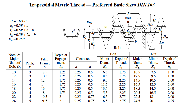
Trapezoidal Metric Thread Nut for a Deckel FP2 X Axis Spindle

This entry documents part of my journey in restoring a Deckel FP2 Milling Machine, I will  share the story on how I got the machine in a separate post, a rare tool in Africa. It does not help that this is my first on making a boring bar for threading, grinding the HSS tool with 30 degree included angle, adding side relief,  and finally cutting a deep internal thread. I could not find any information on dimensions on the internet so I have taken  the decision to share my experience.
The boring bar was made from a length of 15mm drill rod, with a 4mm hole for the HSS tool bit. The flex in the bar made me think a line boring setup might be better suited for production runs, not sure if this is standard practice.
The Trapezoidal Thread for my Deckel FP2 X Axis Spindle, dimensions are close to DIN103, although my machine sports a 4mm pitch. My readings indicate this is not standard to DIN103. Initially I started with ISO 2904-1977 but soon realized the bore of 19mm does not fit the Deckle Spindle, then had to re-bore :/
Ks measured at 19.5mm
Kn (Nut bore diameter) should be 20mm
Dn kept at 24,5mm
DIN103

For Inside Threads, the correct bore size is important, before threading commences.
Step 1 - Ensure inside bore size is correct on entire length of bore. Difficult to fix bore after threading has started, would require new setup/feed speed changes etc. Not good.
Step 2 – Boring bar is parallel to work, insert is at correct height, for brass bronze no back rake. i.e. tool should be perpendicular to work.
Step 3 – tool post is clamped down hard, (with deep internal thread this caused a problem since boring bar shifted, and had to be realigned. Compromising thread quality)
Step 4 – compound should be at 0,5deg less than half the included angle of thread, see infeed methods below. - 14,5 for Trapezoidal internal thread. Slanted back /. http://www.mmsonline.com/articles/threading-on-a-lathe
Step 7 – scratch pass, to establish if feed is correct.
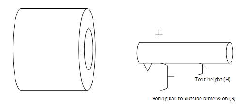
Step 6 - Use boring tool to outside diameter of nut to determine thread depth. Subtract tool height.
Keep going until measurements get close, start fit testing.BoringMeasurement
Outside dimension – (( B – H )  * 2 ) = thread depth
soll wertist wert
outside diameter 4550,457
boring bar to outside16,878517
Tool heightmin 2,53,9
Thread depth24,524,257

Chipmaster Gear Cutting

  Calculate all the possible gear combinations for the gear selector to cut a 15TPI thread: Imperial TPI C 5 24 20 Imperial TPI ...