Showing posts with label deckel fp2. Show all posts

Sunday, 1 July 2018

Deckel FP2 restoration Year 1966, Serial # 5151

Almost two years since I got the machine, and many hours later, the restore is complete. Thanks to www.metalworker.eu, Bruce and some other helpful fellows at https://www.practicalmachinist.com/vb/deckel-maho-aciera-abene-mills/deckel-fp2-1966-restoration-321812/

The machine runs incredibly quiet and is an absolute pleasure to use!


Saturday, 30 June 2018

Surface Speeds - for the Deckel FP2


No more fiddling with a calculator


RPM settings and corresponding surface speeds

Ranges are for HSS tools, extracted from the SO single lip cutter grinder manual. For me, this this is a good starting point for simple cutters. Modern geometries are specified by the manufacturer.

More reading
http://www.stahl-online.de/wp-content/uploads/2013/10/MB137_Zerspanen_von_Stahl.pdf

Sunday, 15 April 2018

Howto on the Horizontal Milling Machine - My notes

Comparing a Deckel FP2 to metal shapers, makes me think they are related, part of the evolution of machine tools. Still want to build the clapper box to fit the deckel...

The problem with the quagga or dodo is they have been extinct for a long time, how they once lived and roamed, we know from information passed down by generations. Very similar to me is the concept of the vertical milling machine, almost extinct; and not a lot of information around on how to use it!?

With the old fossil standing in front of you, and me time traveling with my leather apron, old classics humming on the valve amplifier, I force myself to only use the vertical head, and start thinking how to cut angles as example, it becomes clear; a simple but very useful geometry.

Since very little information is available online, I hope to collect a useful how to guide for starters, and perhaps also gather some expert advice in the field.

In a previous post I presented my idea to cut oil groves with a cutting jig, the jig has to have three sides with angles. How to do this with the vertical head, without sine bar? It would be possible with a swivel base vice if the cutter was very slim and long, not ideal or even possible, sequence of operation becomes important. But on a horizontal setup this becomes easy. Set the angle on the base, flip the part upright, cut the first angle, lay it flat for cut two, flip it over and cut third side. Or reverse the order no problem. Only have a short stubby cutter? also no problem.


Sunday, 11 March 2018

Engraving a cylinder with graduations to be used as machine tool / lathe dial.


Using gcmc to generate the gcode, this becomes a trivial exercise in more modern programming techniques.

feedrate(400.0mm);

sf = 10.0mm;    /* Scaling factor */
diameter = 80.0mm;      /* Scaling factor */

n = 0;

for (c=0deg; c<360deg ; c=c+3.6deg ) {
// message(">>>> ", c, " ",c%36);

 if ( ( c % 36 ) == 0deg || ( c % 36 ) == 36deg) {
 message("--- ", n);
 vl  = typeset(to_string(n), FONT_HSANS_1);
 vl = scale(vl, [sf / (2.0*pi()), sf]);
 n = n + 10;
 goto([diameter/2,-,0.0mm,-,-,c]);
 move([-,-,14.0mm,-,-,-]);

 }
 elif ( ( c % 36 ) == 18deg ) {
 message("--  ", c);
 goto([diameter/2,-,0.0mm,-,-,c]);
 move([-,-,10.0mm,-,-,-]);
 }
 elif ( ( c % 36 ) != 0deg || ( c % 36 ) != 18deg  ) {
 message("-   ", c);
 goto([diameter/2,-,0.0mm,-,-,c]);
 move([-,-,7.0mm,-,-,-]);
 }
}

Interesting site with lathe dial reductions to suit different lead screws.
http://www.modelengineeringwebsite.com/Mini_handwheel_1.html

Sunday, 12 November 2017

Deckel FP2 Horizontal Spindle 1967

Three manuals three stories. I am writing this post to help me make sense of the the information I have at hand, and after reading up on practical machinist forums. There are various tidbits floating around but nothing concise. 

The German manual I have, resembling an old book depicts a spindle very similar in design and layout as seen in the English manual version from 1974. The 1974 manual describes a machine with single wheel speed and feed dials, and external motor. Where the other two manuals describe the two wheel machines with internal motors. However the older English Manual title page has the distinct 70's look seen on other NC Machines, and the font used looks modern compared to the German version. This makes me believe the German version describes the 60's models, the English version describes the early 70's models and the second English version describes later 70's models?

The main differences I can spot are what looks like a second set of needle roller bearings closer behind the first set on the older versions. The English 2 Wheel Manual with 70's font, actually describes these as "loosen 6 tighten 7 to adjust the front roller bearing" further the roller bearing clearance should be a maximum of  .0004"/.01mm. The clearance of the rear roller bearing, is determined by the dimensions of ring 9..." So in this version the needle bearings can be adjusted, implying them to run on tapered sections, which correlates with some information on practical machinist forums. The older German manual does not make reference to this, but the features exist on the drawing. What makes it more confusing is that 6,7 are referring to adjustment rings in the other two manuals, used for adjusting axial clearance on the spindle.

Now the question, what spindle does my FP2 have? The spindle, quill and head bear the engraving 137/137 A with -1.0, which was later 'erased'. This makes me think the parts where custom fit for each machine. With initial test results engraved on the parts, for easier fitting to final machines.
Are some spindles adjustable radially? or is this an error in the manual, introduced by translation/ draftsman in the middle?

Bearing grease to use original KLUBER ISOFLEX SUPER TEL or Franz Singer recommends LDS18
 
If you have more information on the spindle serial numbers, or spindle versions, please leave a comment.

Fig 1. German Manual ( 2Wheel Speed Feed/Internal motor)


Fig 2.  English Manual ( 2Wheel Speed Feed/Internal motor)

 Fig 3. English Manual ( 1 Wheel Speed Feed, External motor)
The entire machine is marked with what looks like a smiley with long eyes  =) anybody know what this symbol represents?


-1.0 Engraved on side of slot, not sure what this means since it was erased afterwards

137 on Spindle shaft, etch process

 A 137 and the erase -1.0 on the spindle quill


Deckel FP2 Serial Numbers

My Serial number and machine marking research summary.

6252 FP2 (2200 type)
2382 FP2E (2205 type)
4491 FP2 (2202 type)
1768 FP2 (probably the 2 motor type)
14893 TOTAL FP2 variants built from 1953 to 1982

FP2 Mill Model Designation:
1953, serial number 45000 (first machine)
1953, serial number 45012
1954, serial number 45141
1955, serial number 45340
1956, serial number 45598
1957, serial number 45958
1958, serial number 45660
1959, serial number 46639
1960, serial number 46640
In January 1960, a new numbering scheme started with 2200/1644
1960, serial number 2200/1892
1961, serial number 2200/2183
1962, serial number 2200/2534
1963, serial number 2200/2995
1964, serial number 2200/3581
1965, serial number 2200/4299
1966, serial number 2200/5149
1967, serial number 2200/5256
last machine produced in the series

FP2E Mill Model Designation:
1958, serial number 46326 (first machine)
1959, serial number 46418 (nur dleso Masch.)
1960, serial numbers 48500 to 48542
In 1960, a new numbering system started with 2205/0046 (ohne Spindelboch)
1960, serial number 2205/0111
1961, serial number 2205/0172
1962, serial number 2205/0196
1963, serial number 2205/0212
Fertigung im April ausgelaufen


FP2-2202 Mill Model Designation:
1967, serial numbers 5301 to 5580
1968, serial number 5925
1969, serial number 6338
1970, serial number 6800
1971, serial number 7399
1972, serial number 7955
1973, serial number 8527
1974, serial number 8993
1975, serial number 9235
1976, serial number 9542
last machine, S/N 9792

1977, serial number 10001
Einhatssupport ab 1954
9196 - 9200
9142 - 9161

Stufe I ab 10001

Ausfrus??? fur X-Mo?stab ab 9150 - 9792
v. Shulf I - 10001 ... 2202

1980, serial number 11009
1981, serial numbers 11010 to 11434
1982, serial number 11769

Die Masch. -Serien-Nr. ist auf dem Firmenschild - am StänderfuB in
Hohe der oelablassschraube vom Vorschubgetribe u. am Staender oben -
sichtbar wenn der Spindelbock in ruckwartiger Stellung - eingeschlagen.

Saturday, 27 May 2017

Deckel FP2 Vertical Column Scraping


After numerous iterations of blueing, scraping measuring and head scratching, I placed the saddle back and did some measurements with reference to the original machined surface on the vertical columns, here the results. granite parallels where placed between the ways on the machined surface, and a straight-edge spanning over it, and finally the measurement was taken from the top of the saddle to the straight-edge which are now in the same plane.

Y Represents the distance in cm from the top of the main column body.
x(0) represents the right outer measurement (over right column) , x(1) the center between columns, and x(2) the left outer measurement( over left column). The error is not nearly as big as originally measured, but it seems like the saddle nose dives into the worn area on the right column caused by the rusting cover plate. Then climbs back out and rises on the left top column section by 0,008 mm. I have repeated the measurements a few times to be certain. More scraping work on the left upper column will bring the saddle movement back within spec. no need to cast moglice or turcite. I will probably just scrape the back gib a bit to compensate. The measurement is in line with what I measured when testing the right back gib for parallelisms to the way. 
Visualization with https://plot.ly/create/


Left Front Center Right Front
0 0.004 0 0
10 0.009 0.001 0
15 0.006 -0.002 0
20 0.003 -0.002 -0.003
25 0.002 -0.002 -0.002
30 0.002 -0.001 -0.001
35 0.003 -0.001 -0.001
40 0.004 -0.004 -0.006
45 0 -0.004 -0.008


Sleeping over it, made me think, there might be other reasons why I get the measurements.
  • it might related to leveling of the main column body. 
  • The right back gib was not mounted, which could indicate a slight tilt in the left column way
  •  The worn area on the center of right column might cause the saddle to lift the right front part when the left rear dips into the worn area.
I have redone the measurement of the column height with reference to the machined surface, and get very similar results, thus at this point I will slightly scrape the top part of the left front column and call it job done. Next step would be to start with the saddle.

Thursday, 6 April 2017

Trapezoidal Metric Thread Nut for a Deckel FP2 X Axis Spindle

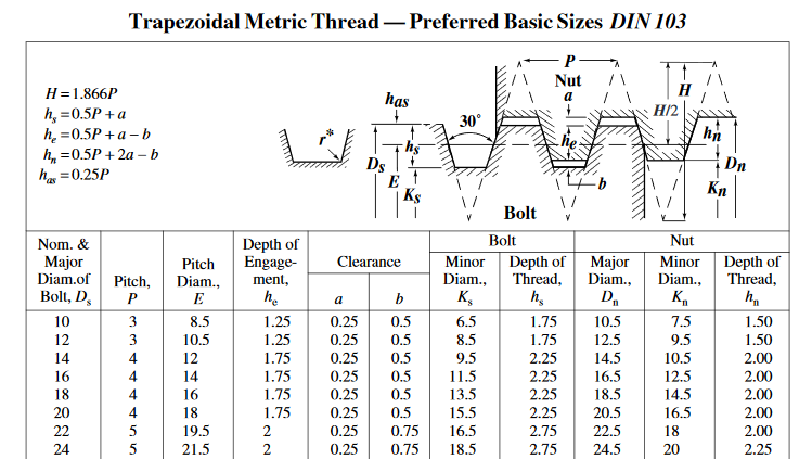
This entry documents part of my journey in restoring a Deckel FP2 Milling Machine, I will  share the story on how I got the machine in a separate post, a rare tool in Africa. It does not help that this is my first on making a boring bar for threading, grinding the HSS tool with 30 degree included angle, adding side relief,  and finally cutting a deep internal thread. I could not find any information on dimensions on the internet so I have taken  the decision to share my experience.
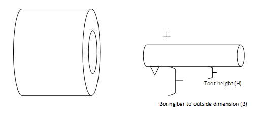
The boring bar was made from a length of 15mm drill rod, with a 4mm hole for the HSS tool bit. The flex in the bar made me think a line boring setup might be better suited for production runs, not sure if this is standard practice.
The Trapezoidal Thread for my Deckel FP2 X Axis Spindle, dimensions are close to DIN103, although my machine sports a 4mm pitch. My readings indicate this is not standard to DIN103. Initially I started with ISO 2904-1977 but soon realized the bore of 19mm does not fit the Deckle Spindle, then had to re-bore :/
Ks measured at 19.5mm
Kn (Nut bore diameter) should be 20mm
Dn kept at 24,5mm
DIN103

For Inside Threads, the correct bore size is important, before threading commences.
Step 1 - Ensure inside bore size is correct on entire length of bore. Difficult to fix bore after threading has started, would require new setup/feed speed changes etc. Not good.
Step 2 – Boring bar is parallel to work, insert is at correct height, for brass bronze no back rake. i.e. tool should be perpendicular to work.
Step 3 – tool post is clamped down hard, (with deep internal thread this caused a problem since boring bar shifted, and had to be realigned. Compromising thread quality)
Step 4 – compound should be at 0,5deg less than half the included angle of thread, see infeed methods below. - 14,5 for Trapezoidal internal thread. Slanted back /. http://www.mmsonline.com/articles/threading-on-a-lathe
Step 7 – scratch pass, to establish if feed is correct.
Step 6 - Use boring tool to outside diameter of nut to determine thread depth. Subtract tool height.
Keep going until measurements get close, start fit testing.BoringMeasurement
Outside dimension – (( B – H )  * 2 ) = thread depth
soll wertist wert
outside diameter 4550,457
boring bar to outside16,878517
Tool heightmin 2,53,9
Thread depth24,524,257

Friday, 17 June 2016

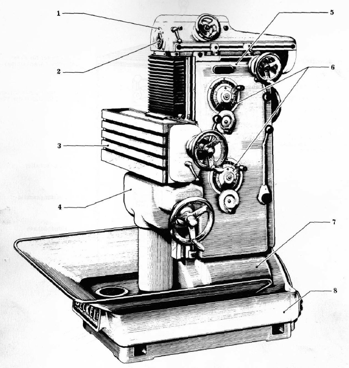
Deckel FP2 Milling Machine 1967


In May 2016, while still trying to figure my affection with old iron, to my surprise, I stumbled on a advertisement for a Deckel Milling Machine. In my mind I was convinced these machines do not exist in Africa.  After pondering if a 1.5 Ton Tool is the right choice for the home workshop, I made the decision and managed to persuade the owner to honor my first offer. Next came planning the logistics for the 2000km transport to my home town. Well knowing these machines are top heavy I tried to convince all the parties involved to take every precaution to prevent the machine from tipping over. All went well until the last delivery leg from the depot in town to my home. When the driver driver got there, I asked him if all went ok, he shrugged his shoulders and said, he think there was a thumping noise in the back of the truck. ohhh no.
After inspecting it became evident that the machine was not rigged in any way and toppled over.
So this is the start of my journey to restore this versatile and sturdy build machine, what a daunting and challenging task, with no prior experience I jumped right in!
Scouring the net for manuals I found Den Tukker's site http://www.metalworker.eu/metaalwerk/htmlen/index-machines.htm, nice gentleman who shares some insights. It seems he also collects great old machine tools.
Source of Deckel manuals:
https://onedrive.live.com/?id=547FE296ECFD561F!209&cid=547FE296ECFD561F

Chipmaster Gear Cutting

  Calculate all the possible gear combinations for the gear selector to cut a 15TPI thread: Imperial TPI C 5 24 20 Imperial TPI ...