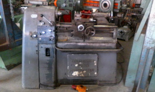
To regrind the Chipmasters bed I will need to balance the wheel and spindle. I
was thinking along the lines of using a gyro, accelerometer device
like those found in your smartphone or drone, then measure displacement
and rotation to identify imbalances.
This site hosts some interesting articles drkfs.net, including a balancing technique http://drkfs.net/balancedisk.htm
another device based on the above design:
http://www.turbinemuseum.de/Gasturbines/Balancing_Tool/balancing_tool.html
Balaancing a brushless motor and propeller with a similar method:
https://github.com/QuadTinnakon/Arduino-Balance-a-Brushless-Motor-and-Propeller-Balancing-/blob/master/Balance_Mega2560_V5.ino
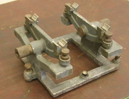
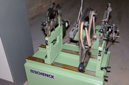
Old Static wheel balancing device.
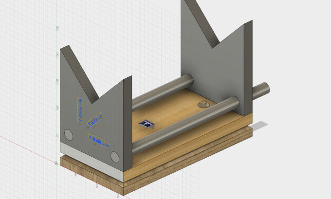
My Design
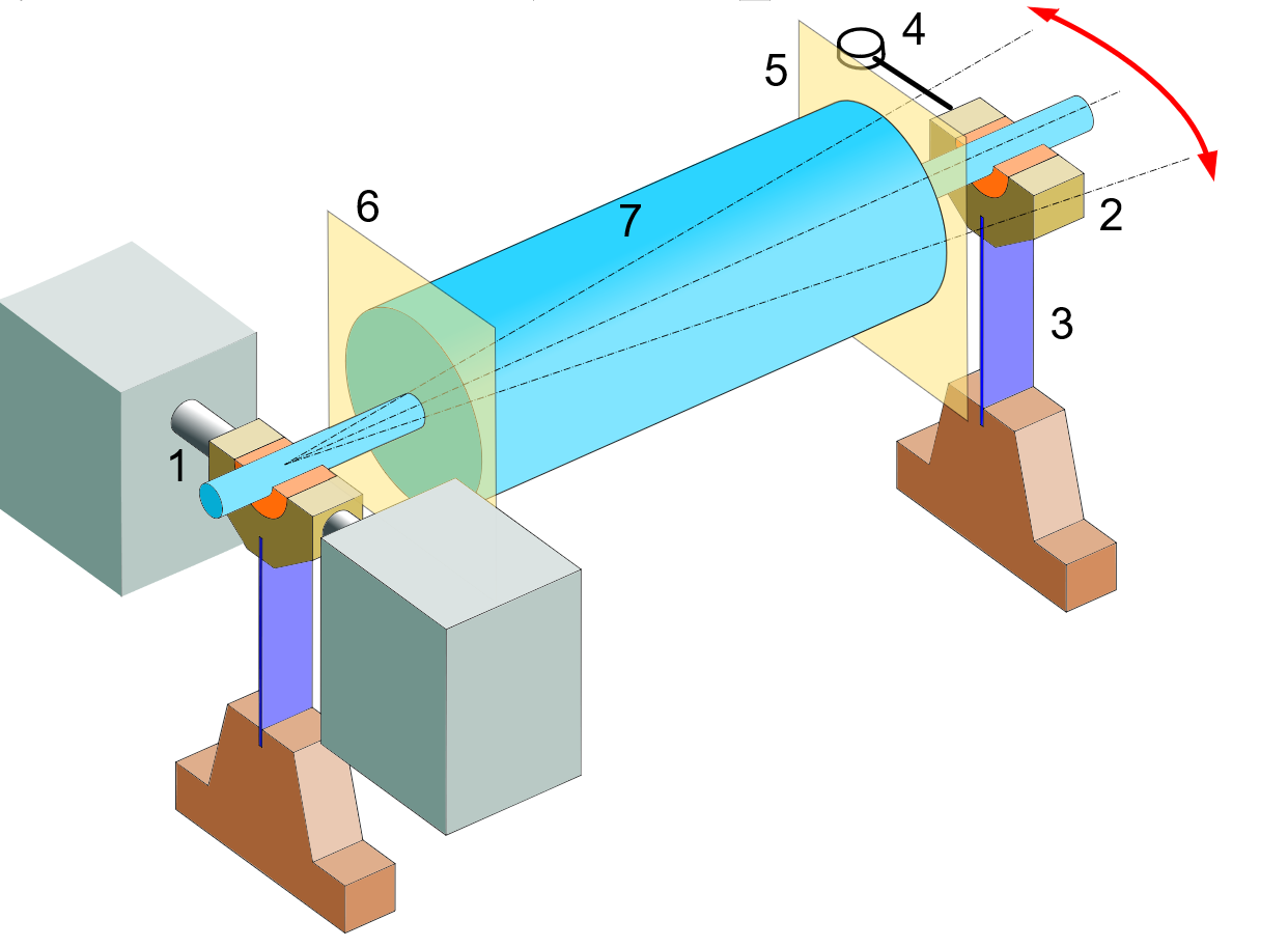
This
is a fixture where the top is floating on three braided steel wire
pivots. The wire is aligned to provide freedom of movement along the
horizontal axis (x). Mounting a 3 axis accelerometer on the floating
base should be able to measure the vibration caused by the out of
balance mass of the rotating body overhead, in the x and to some lesser
degree in y and z plane. I have not done any calculations on the
geometry and actual vibrations expected, to be able to predict the mass
required to correct the out of balance.
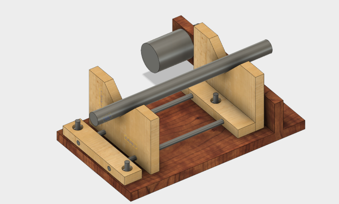
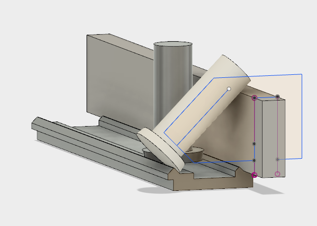
Take Two
Simplified, and improved design and more complete layout.
Balancing a Rotating Object using an Accelerometer, type MMA2301
The setup described here is a small scale version of the wheel-balancing machines used in auto mobile tyre fitting workshops. It was required in the course of the development of an instrument with a multi-component rotating part which needed to be more or less vibration free at about 5000 rpm. Initial steps were taken to ensure that the disk was nearly balanced from the start. Each component of the rotating sub assembly were weighed at the design stage and mounted, as far as possible to balance one another about the intended axis of rotation. The result was a rotating sub-assembly which ran smoothly up to about 500 rpm but showed about 5g of vibration at 5000 rpm. The setup described here was designed to measure and correct the imbalance causing this vibration.
The Optical Tachometer
A simple optical tachometer was set up to provide a timebase for the measurements. A rectangular block of perspex, approximately 15 x 6 x 5 mm was used as the supporting element of the tachometer. To one of the small ends, an IR880 LED and an OP501 phototransistor were cemented using epoxy resin, and wired to a 5 volt supply via resistors as shown in the sketch above. The section of the motor shaft was painted matte black and attached to it longitudinally, a strip of aluminium foil about 0.3mm in width. As the motor rotated, this strip reflected light from the LED to the phototransistor once per revolution and generated an electrical pulse about 0.05 -0.1V in height, sufficient to provide a reliable trigger for an oscilloscope. The tacho signal from the collector of the phototransistor was supplied to one Y channel of a Telequipment DM63 Analogue Storage Oscilloscope, set to 50mV/division and 2mS per division on the timebase.
The motor was a high-quality brushless DC type, having a control voltage input supplied from a 10 turn potentiometer to enable good manual control over the motor speed.
The Accelerometer
The vibration caused by the out of balance mass on the rotating sub-assembly was detected and measured by a single axis solid-state accelerometer, type MMA2301. The data sheet for this device is available
here.
The simple electrical configuration of this device is shown in the diagram above. It provide a voltage output proportional to the acceleration at the rate of 10mV/g. Its output was applied to a second Y channel of the DM63 Oscilloscope, set to 20mV/division.
The Measurements
The trace obtained when an out-of-balance object is rotated on the shaft is shown diagrammatically on the oscilloscope screen at the head of this page. The analogue storage facility was used to capture the trace which was then photographed. Two measurements can be taken from the resulting photographs. The more important of these is the phase interval T, in the diagram, which is a measure of the time, and hence the angle, between the tacho zero and the maximum out of balance mass. This allows the determination of the angular position of the total out of balance moment about the rotational axis. To counteract this an equivalent moment must be added to the object 180 degrees from the determined position. The oscilloscope screen photo below shows the trace obtained from the unbalanced object. The upper trace is the tacho signal showing the zero pulse. The lower trace is the accelerometer signal which has an amplitude of some 70 mV, corresponding to a vibrational acceleration of 7 g.
Calculation of the required mass.
The following is a method for obtaining an approximation to the required mass, and depends upon the assumption that the vibrational acceleration measured by the accelerometer on the base plate supporting the motor is equal to the out of balance acceleration on the rotating object. This is a reasonable approximation if there is little shock absorption on the mountings.
If the linear acceleration at the periphery of the rotating object, radius r and mass M , owing to its revolution at an angular velocity ω, is A, and the measured vibration acceleration is a, we can express the approximate relationship as:
m = a.M/r.ω2
where mis the extra mass at the periphery. Using this equation, the additional mass was calculated and applied to the rotating sub assembly at the correct position on it periphery. Retesting the vibration amplitude demonstrated that the required mass was, in fact, twice the calculated value. When this mass was added, the result obtained showed a very small vibrational amplitude, and the rotation was smooth up to 5000 RPM. The screen photograph below shows the trace obtained.