1) Align the tail-stock on the mill, and touch-up the V slot, and flat surface. Machine one outside surface parallel to the V-Groves. Final fit on the lathe with transfer spotting.
2) Find the best reference surface on the carriage with the fitted tail-stock base as guide. Or bolt an adjustable bar to the back, where the taper attachment usually attaches.
3) Machine the cross-slide base V and flat ways, aligned to identified surface. Fit with transfer bluing.
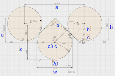
The calculation for the depth of the V slots require similar math to that used for dovetail calculations. I used two 14 mm end mills as gauge pins, the bottom circle is used for measuring the depth, when the base is upside down on the mill, since I want to do the machining in one setup.
On the drawing, the top two 14mm gauge pins are used to measure the_ /\_ ways, the
bottom gauge pin is used to measure height over the flat surface, for a level tail stock base.
map the flat surface to find low points, add z, mill out v until this height is reached
mill down flat surface

measured 38,515 across pins
c1,c2,c3 r 7
a 24,515 measured-2r
b 4,949747468
c 2,050252532 r-b
2d 14,61550506
d 7,307752532
h 9,358005063 c+d
w 18,71601013 2*height
e 9,899494937
c3 center 0,541489873 e-h
z 7,541489873 r+c3 center

No comments:
Post a Comment